Well after looking at the latest AMRM it has got to a stage when something must be said and done regarding the constant disregarding of certain rules as applied to modelling.
For some that count rivets and perhaps dwell on the shape and curve of the 42 class nose, or the correct shade of green for a 38, when it comes to modelling a corrugated iron roof all common sense and intellect built up over years surviving on the planet are carelessly thrown out the window and the raving lunatic personality from within takes control like a bad scene from Alien.
This results in atrocious looking structures that look nothing like the real thing, all based on the pretense that if a corrugated iron roof is constructed in real life with individual sheets then the best way to model this would be to use individual sheets
NO ITS NOT !
Most layouts are built too low, giving the impression of the view from a plane, so getting the roof right is more important than ever.
Please allow me to explain.
A quick lesson in some of the finer points of corrugated iron.
Galvanised iron's introduction to Australia dates back to 1837 with the introduction of corrugating and curving machines around this date to various states and also imported iron from England being used. Imports for 1894 totalled 170,000 tonnes.
With its acceptance and easy use making it widely used around Australia in ever increasing quantities.
As with any new invention it took a while for the most acceptable style or design to become entrenched and dominate (Hands up all those BETA and 8 track owners).
By the 1890's the common pitches available were 3, 4 and 5 " of varying thicknesses, with each manufacturer having a small variation in pitch and depth.
The one we shall deal with is the overall winner of the standardisation contest being the 8/3 inch corrugations, meaning the sheet had 9 high corrugations at 3 inch centres and 8 low corrugations or valleys at 3/4 inch depth, with each side of the sheet having a downturn. The sheets came in 5, 6, 7, 8, 9 and 10 ft lengths and could be 18/20/22/24/26/28 in gauge or thickness.
This early iron was a more ductile than the present hi-tensile iron used today for roofing
The most common gauges used were 26 for roofing with the heavier 24 used for curved bullnose verandas, veranda awnings and 22 or 24 gauge for tank making. The lighter 26 gauge could not be curved.
The Birmingham Gauge used for this standard is not the same as the Birmingham wire gauge.
With every 6th decrease in the gauge number giving a doubling in sheet thickness .

Because these 8 corro sheets had a down turn on both sides as opposed to 1
down and 1 up as with the current 10 and a half corro sheet used today
(more on this latter), for cladding a wall 1 corrugation of lap was adequate. But for roofing to be water proof 1 1/2 corrugations was acceptable but 2 was extravagant.
To sheet a roof and have enough lap on the sides of the sheets to be weather proof, 2 methods where used which gave 2 very different appearances .
Method
1
The old 1 over and 1 under trick meant that every alternate sheet was
turned over so as to give 1 1/2 corrugations of lap.With the under sheet
showing a much narrower width than the next full over sheet.
So the full width over sheet would show 660mm or 2' 6"
And the under sheet would show 490mm or 19 and 1/4 "
Method 2
The sheets are laid from one direction with one side of the sheet being an under the other side being an over or 2 corrugations of lap. This gives a more uniform (in sheet width) roof appearance.
The direction of the overlap can be determined by the prevailing weather or the viewing direction so as not to see all the side laps or just the easiest direction to put on the sheets.
So each sheet would show 525mm or 20 and 5/8 "
Some of the more astute viewers would recognise this as the local G I cop shop roof.
With the introduction of the wider 10 and 1/2 corro sheets possibly around the 1950's things change in the overall look of a roof. These sheets have 1 up and 1 down corrugation on the sheet sides, so that 1 1/2 corrugations of lap are able to be used. With the overall sheet width of 860 mm and a cover of 760 mm being visible on the finished roof. These sheets were originally available in standard increments of 1 ft in lengths up to 10 ft. But now the delivered length is only restricted to your ability to transport the length legally.
As for the cover show on the length of the sheets. The lap would be at least 6 " so 2 x 8 ft sheets would cover 15 ft 6" not 16 ft.
Bullnose verandas still use the same 8 corro sheet of a thicker curving grade, but used only 1 corrugation of lap which was usually riveted together .
So the sheet would show 23 and 5/8" or 600mm
Which brings us back to the modelling of roofs correctly. (Remember)
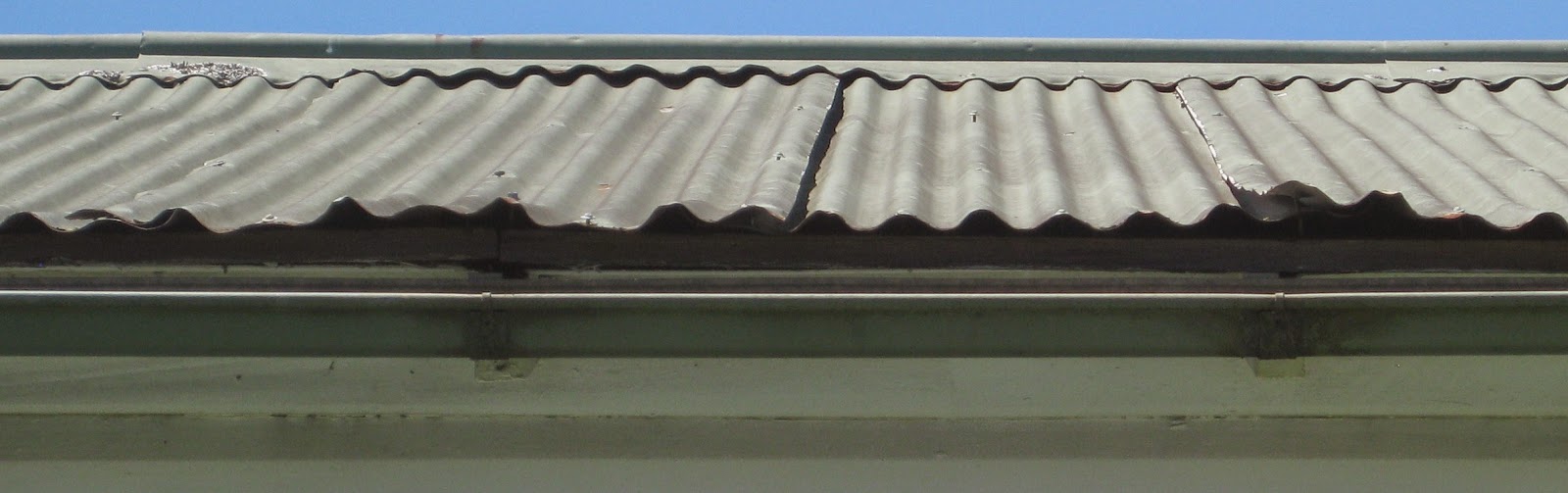
As with any modelling, a time period needs to be determined not only for the roofs initial construction but more importantly the era being modelled. For an example, a roof installed in 1910 but modelled for 2010 would be in a poor condition.and probably painted. If an unsupported bullnose veranda is on this building the iron would be pushed down and out of shape usually from fat arsed painters using it for a scaffold without a plank or stepping down on to it from the main roof. But if the same roof is modelled for 1920 it would be near new and unpainted. Plus what width and length of sheeting to be shown ?
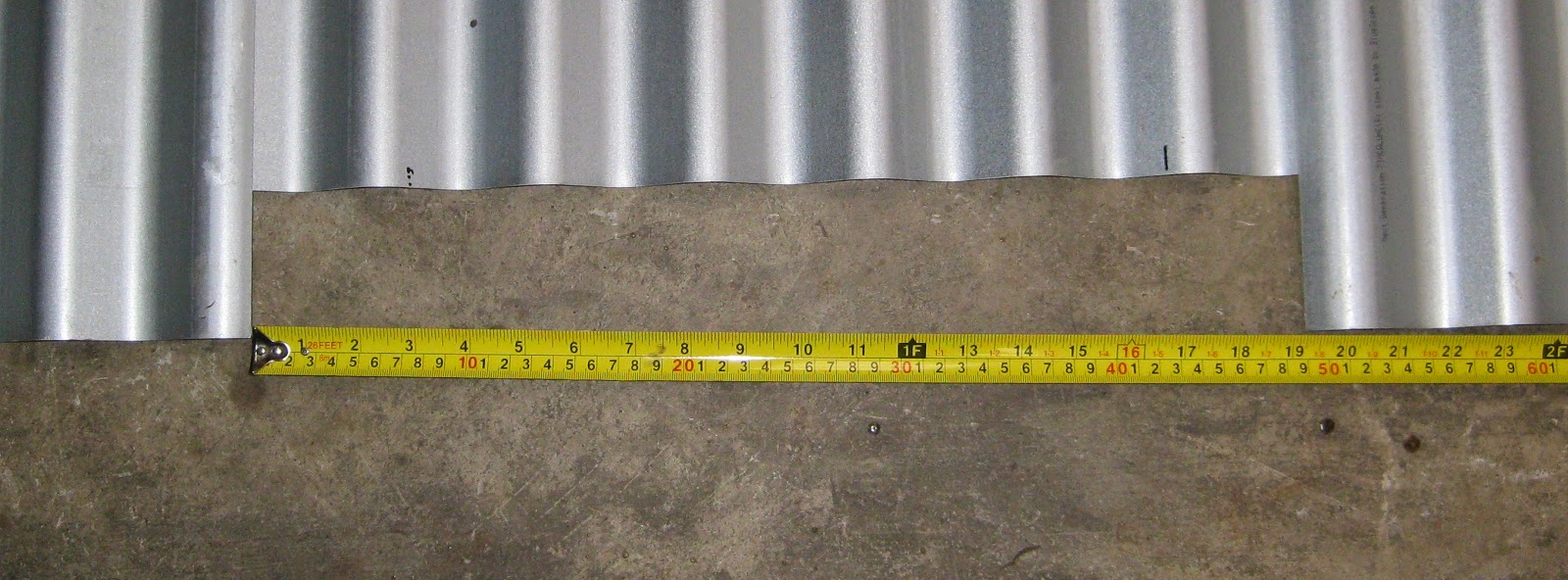
One must remember that when installing individually cut sheets on a model that if the sides or ends of the sheet stick up more than .5mm the real life sheet would be sticking up 1 3/4 ". This does not represent normal old roofs but an abandoned house with a roof ready to be blown away. This was the main reason for this post to stamp out this ridiculous practice once and for all.
When modelling roofs I like to use corrugated card or aluminium sheets to cover the entire area then mark out the width and length of sheet.being modelled. Then using a fine pencil draw in the lines or lightly scribe with an exacto knife.
The roof of my A depot modelling 10 and 1/2 corro 7 ft sheeting
I don't attempt to model loose sheets on in-use buildings as the dimensions are just to small . And don't forget to get the ridge, valleys and barge rolls the right length too !
e